in a Surface Plot
As noted in the writeup for the Define Boundary command, DPlot generates a convex triangular mesh from your input 3D points. DPlot must assume a boundary shape, since a table of X,Y,Z points contains no connectivity information or any clues about which points define the outside edges of the surface. The assumption of a convex boundary works out well in many cases, but of course in some cases is inappropriate. And in no case will the generated triangular mesh accommodate interior holes in the surface.
The procedure for defining interior holes is much the same as that for defining a concave boundary: by use of the Define Boundary command. The trick is to ensure that the path along the border from the exterior of the surface is exactly the same, but in the reverse direction, as the path from the hole back out to the exterior edge. As an example, this plot:

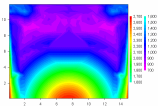
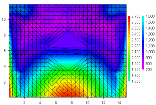
depicts peak pressure measurements across the face of a wall with an opening in the center of the wall. No gauges were located within the opening, so the plot is at best misleading. If you use the Contour Options command to turn on the triangle borders then the opening location becomes more apparent:

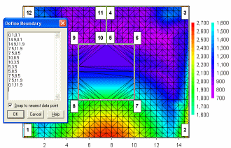
You can use Define Boundary to remove all of the triangles inside the opening. In the example shown, the points picked as the border are numbered 1-12, starting at the lower left corner and proceeding counterclockwise around the surface. Note that point 4 (at the top of the surface) is the same as point 11 and point 5 (at the top of the hole) is the same as point 10. In short, the path taken from the exterior edge to a hole can be anywhere on the surface as long as the exit path lies along those same points. For best results (to avoid roundoff errors) the entrance/exit path should be vertical or horizontal.

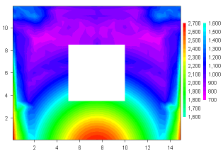
Finally, here is the result of using Define Boundary to remove triangles from the opening:

Privacy Policy